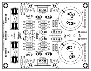
This
PSU could, theoretically, supply up to 8A for short periods, with the output
sagging to ±14V at that current, but it will never be asked to supply anywhere
near that much in the intended application and I would rather not push it to
the limit in case I break something.
It's
a capacitance multiplier. These work by amplifying an RC filter, rather than a
voltage reference as a normal regulator does. It has certain benefits over a
regulator, including lower power dissipation and smoother output ripple (high
frequencies are attenuated more than low frequencies). It's improved compared
to the usual design that is seen (emitter-follower buffered RC filter) with
increased ripple rejection and/or smaller RC filter capacitor due to high input
impedance, and lower dropout voltage due to use of pass transistors of opposite
polarity to normal (limited only by RDS(on) multiplied by output current for
MOSFETs, or VCE(sat) for BJTs). The cost is increased complexity, with six
transistors used per rail.
The
mosfet contained in the layout is only an option, you can also use other series
mosfet such as Mosfet IRF3205 & IRF4905 / IRF3710 & IRF52101 / IRF540
& IRF9540, Etc.
The
design above does not include a psu snubber, so for connection to an amplifier
like the chart below.
Official website : https://mrevil.asvachin.com/amp/amp4/sub/psu2/
Select the chat option in the sidebar menu if there is a
dead link!
Download link (Google Drive):
Gerber


Comments
Post a Comment